
Separate duties
Equipment, neutral and lightning earth duties should stay identifiable. A low number at one chamber does not prove every route.
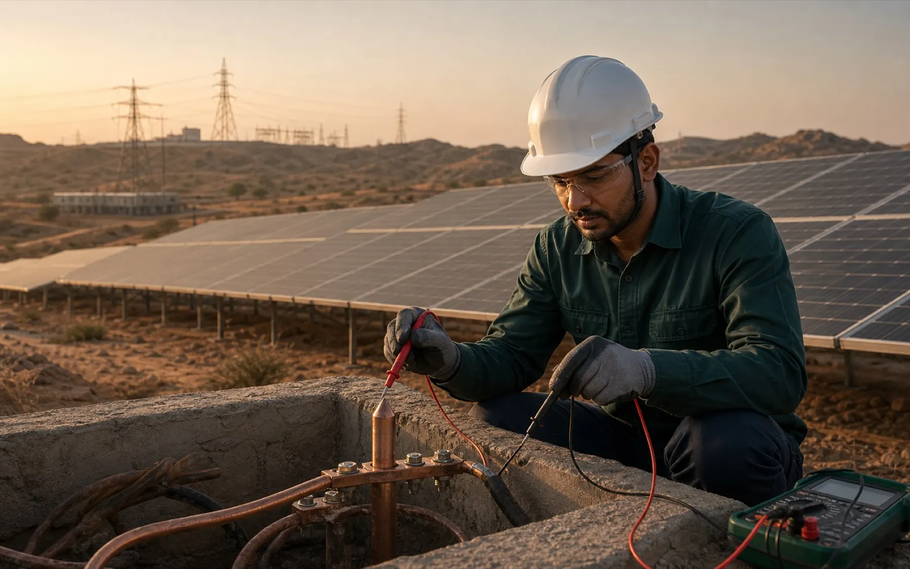
Solar plant application
Coordinate solar plant earthing, bonding, lightning protection and testing around array, inverter, transformer and site-specific duties.
Discuss the project inputsDirect answer
Treat the plant as one network. Exposed module structures, DC and AC equipment, inverter stations, transformers and lightning protection need coordinated paths under the approved electrical design.
There is no universal pit count. Soil data, fault duty, bonding, route length, separate earth spacing and accessible test points decide the layout and commissioning record.
Equipment, neutral and lightning earth duties should stay identifiable. A low number at one chamber does not prove every route.
3E lists 2, 3 and 6 metre electrode lengths. The selected model must be installed at its full length.
Record pit identity, method and connected condition. Bond continuity needs evidence beyond the electrode reading.
Technical view
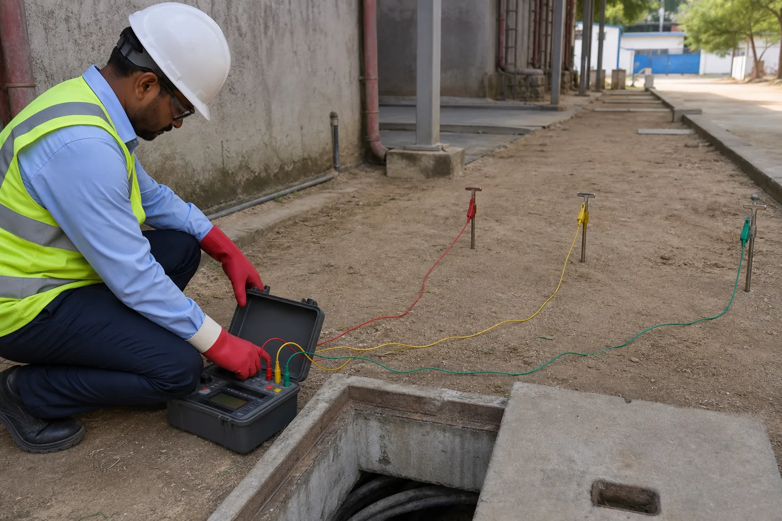
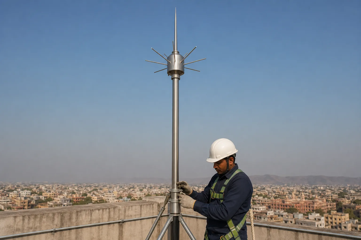
Map the metal first. Module frames, mounting structures, inverter enclosures, transformers, panels, cable containment and lightning components each meet the protective network at defined points.
Do not infer continuity. Long rows, mechanical joints and painted or oxidised interfaces can interrupt a route that looks connected from a distance.
Distance adds interfaces. Utility-scale sites have repeated joints, exposed conductors and many test identities, while rooftops have tight routes around waterproofing and occupied spaces.
Label the branches. A clear register lets commissioning and O&M teams find the weak section instead of treating every poor result as an electrode problem.
They meet at interfaces. External interception, bonding, cable entry and coordinated surge protection should be reviewed together because a rooftop terminal cannot control every conducted transient.
Keep the claims narrow. Published ESE radius tables depend on model, protection level and tip height, and they do not replace a structure-specific assessment.
Decision sheet
The MW rating is not enough. Procurement needs the duties, routes and acceptance evidence behind the quantities.
Working sequence
The useful trail survives commissioning. It lets a later technician connect a reading to the asset it protects.
Identify array, inverter, transformer, equipment and lightning earth paths on the drawings.
Set conductor, bonding, surge and containment interfaces before repetitive installation begins.
Keep full electrode length, clear spacing, accessible joints and durable earth identities.
Record continuity and resistance evidence with the method and connected state.
Questions that change the scope
No. Soil, fault duty, layout, equipment and the approved design decide the count.
No. Follow the approved bonding and earth-termination design instead of guessing from labels.
No. The conductor route and every mechanical or electrical joint also need verification.
No. Capacity is one context item, not a substitute for soil, fault and network data.
Send the real inputs
Send the plant layout, single line, array and inverter arrangement, lightning drawings, earthing schedule and commissioning requirement. We will mark missing system interfaces.
Send the requirement on WhatsApp