
Eurostar ES.60
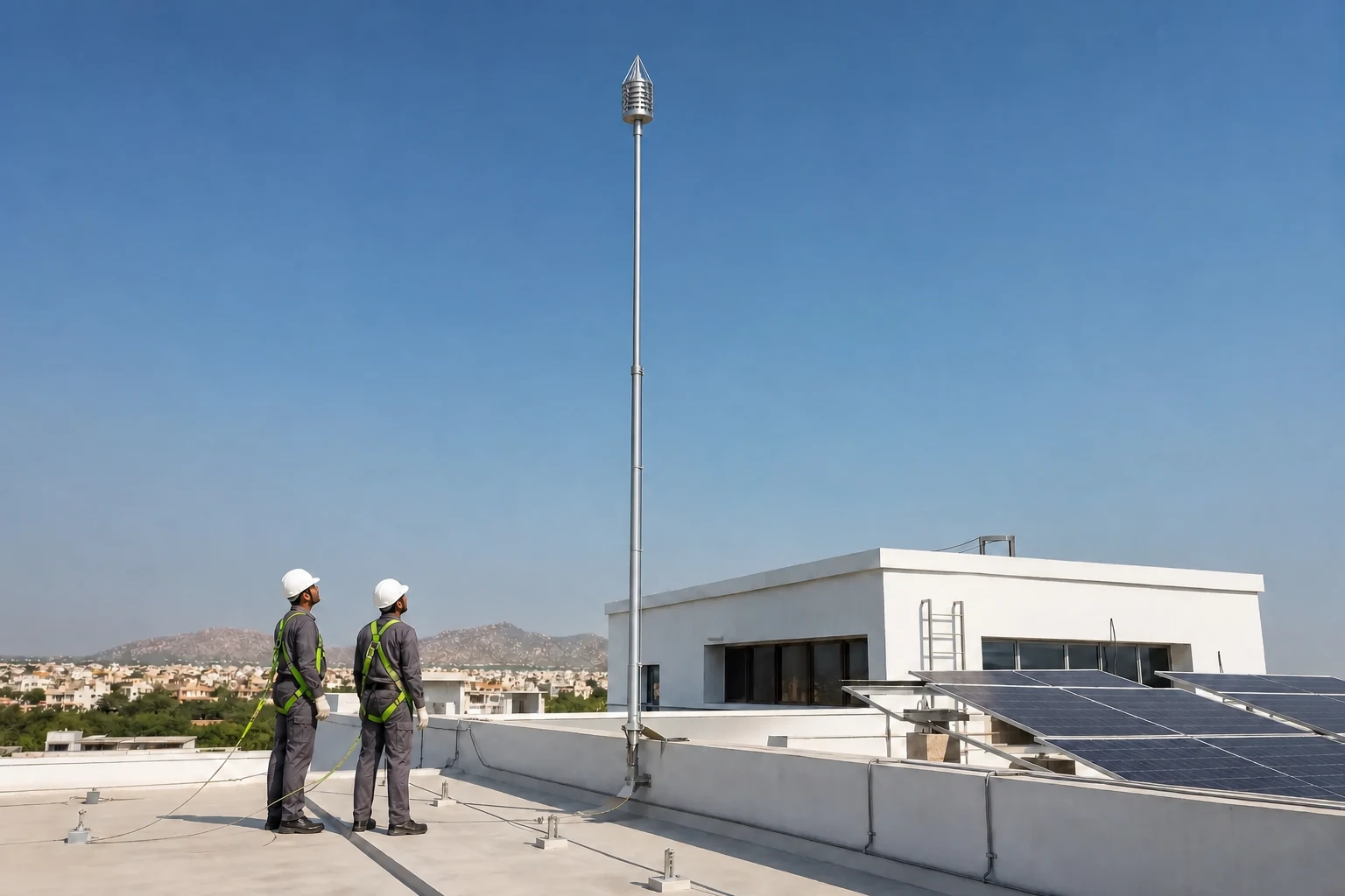
The ES.60 is a non-electronic 316-grade stainless steel ESE terminal with a published 60 microsecond initiation advance.
Lightning protection
Conventional IEC and Eurostar ESE lightning protection systems for solar plants, factories and buildings in Jaipur and across Rajasthan.
Discuss your requirementStart here
The air terminal is only the visible part. A working system also needs a planned protection zone, down conductors, bonding, surge coordination and an earth termination network that can carry the event safely.
3E Solutions supplies conventional systems designed to IS/IEC 62305 and Eurostar ESE air terminals designed to NF C 17-102. A risk assessment, roof geometry and conductor routing decide the final layout. A taller rod alone does not.
The ES.60 is a non-electronic 316-grade stainless steel ESE terminal with a published 60 microsecond initiation advance.
Roof networks can use 25 x 3 mm GI strip or 8 mm aluminium conductor where the approved design calls for it.
The ESE installation schedule specifies a mast at least 2 metres above the highest protected point.
Technical view
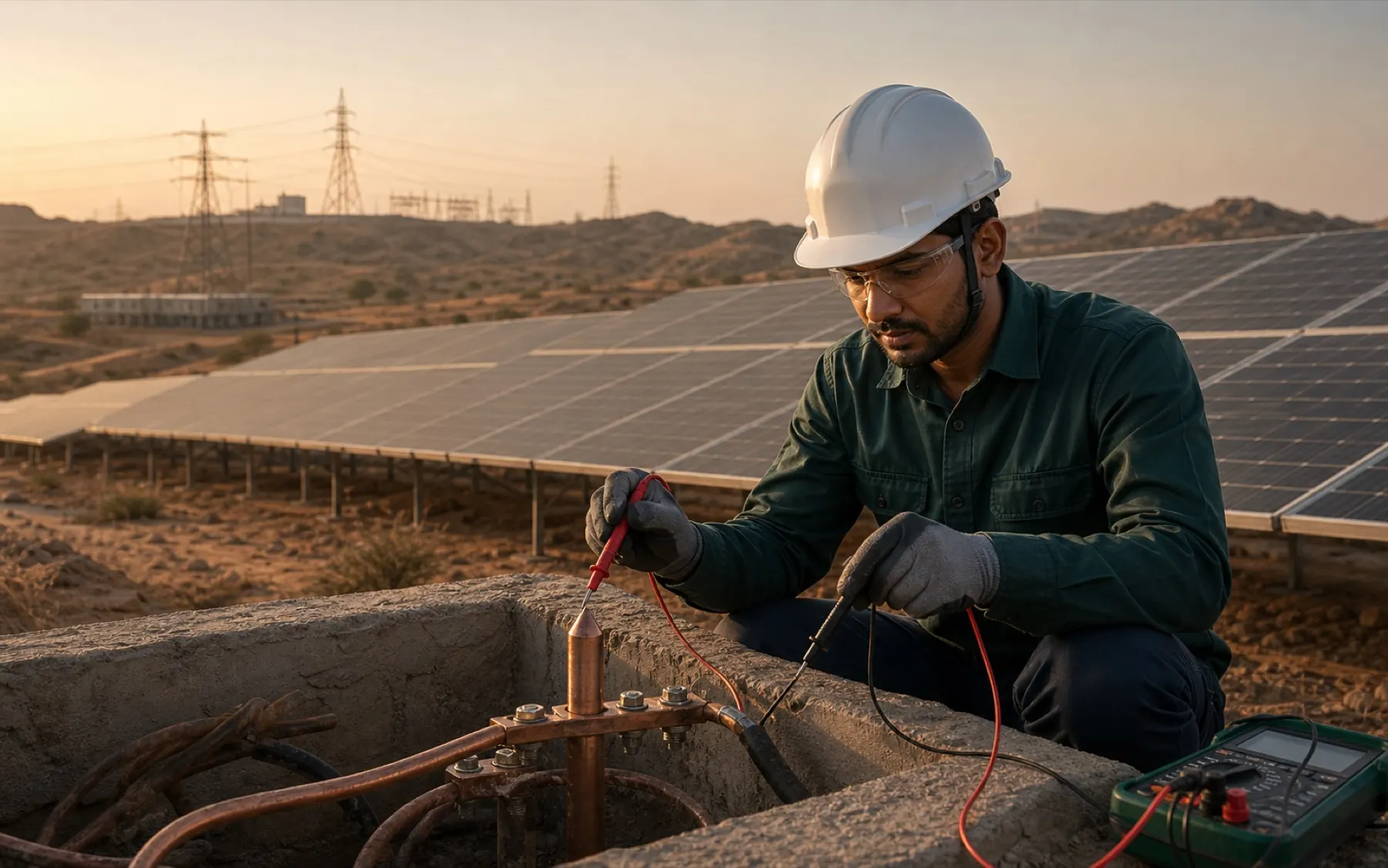
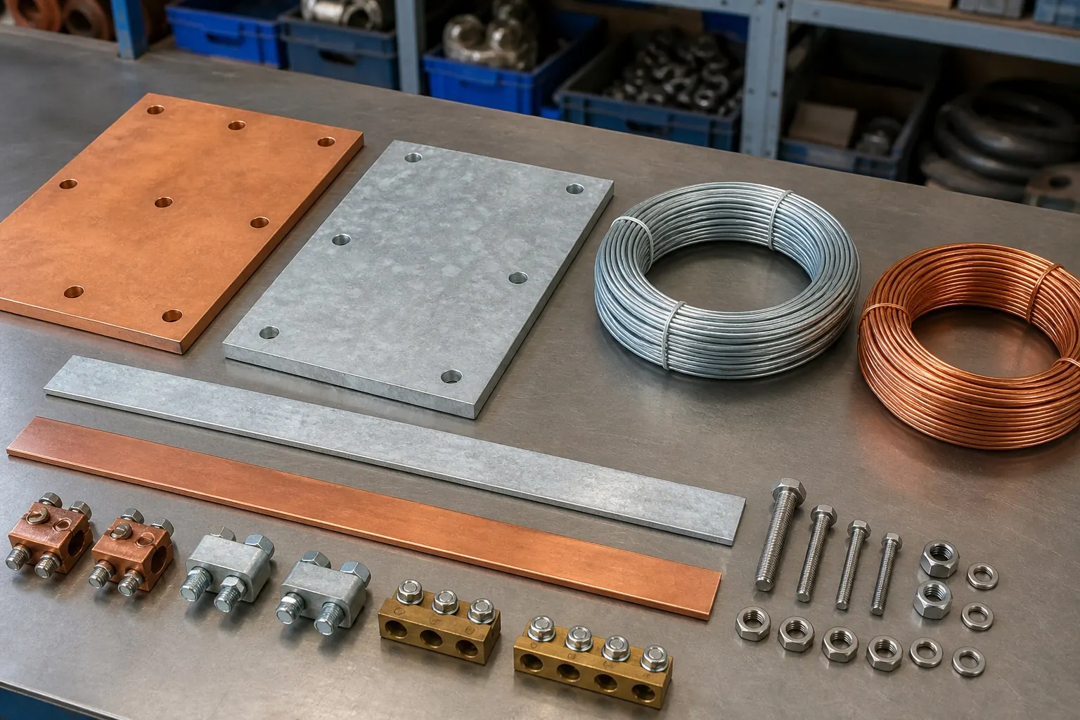
A conventional IS/IEC 62305 arrangement places air termination and conductors around the actual roof geometry. The approved design may use 25 x 3 mm GI strip or 8 mm aluminium conductor along the parapet, with down conductors, bonding and earth termination shown together.
This method is not a row of decorative spikes. Roof equipment, separation, bends, test joints and surge coordination all change the finished system.
The supplied Eurostar schedule describes a non-electronic terminal with a 60 microsecond initiation advance, 316-grade stainless body and six auxiliary rods. It lists a 79 metre radius at Protection Level I only when the terminal tip is 5 metres above the protected surface.
The manufacturer letter dated 1 January 2020 authorises Rakesh K Jain and 3E Solutions for enlistment and supply for PWD BSR Jaipur, unless withdrawn. Current territory beyond that wording should be confirmed for the project.
Explore this product family
Specification
A useful survey looks at the whole path. Roof height is one input, but it is a poor description of the actual risk by itself.
Method
Start with risk and geometry, not a catalogue radius. The chosen method still needs a continuous, inspectable path to earth.
Capture roof levels, equipment, access and the surrounding exposure.
Set the protection approach against the project brief and applicable standard.
Route down conductors and bonding before clashes are buried in the site work.
Record continuity and earth readings, then keep inspection points reachable.
Questions from site and procurement teams
No. Terminal count and method follow the risk assessment, protection level, height and building geometry. Published radius data cannot replace a project layout.
The supplied Eurostar schedule states a minimum of 2 metres above the highest protected point. The published radius also depends on the terminal tip height above the protected surface.
No. External lightning protection handles the strike path outside the structure. Surge protection and equipotential bonding address different parts of the electrical risk.
The supplied 3E schedule calls for yearly inspection of the terminal, down-conductor continuity and earth resistance under the referenced maintenance standards.
Bring us the site details
Send the roof plan, heights, site use and exposed equipment. We will begin with the risk inputs before discussing conventional or ESE hardware.
Contact 3E Solutions