
Stated design basis
3E lists lightning risk assessment and LPS design under IS/IEC 62305. The agreed edition and deliverables belong in the proposal.
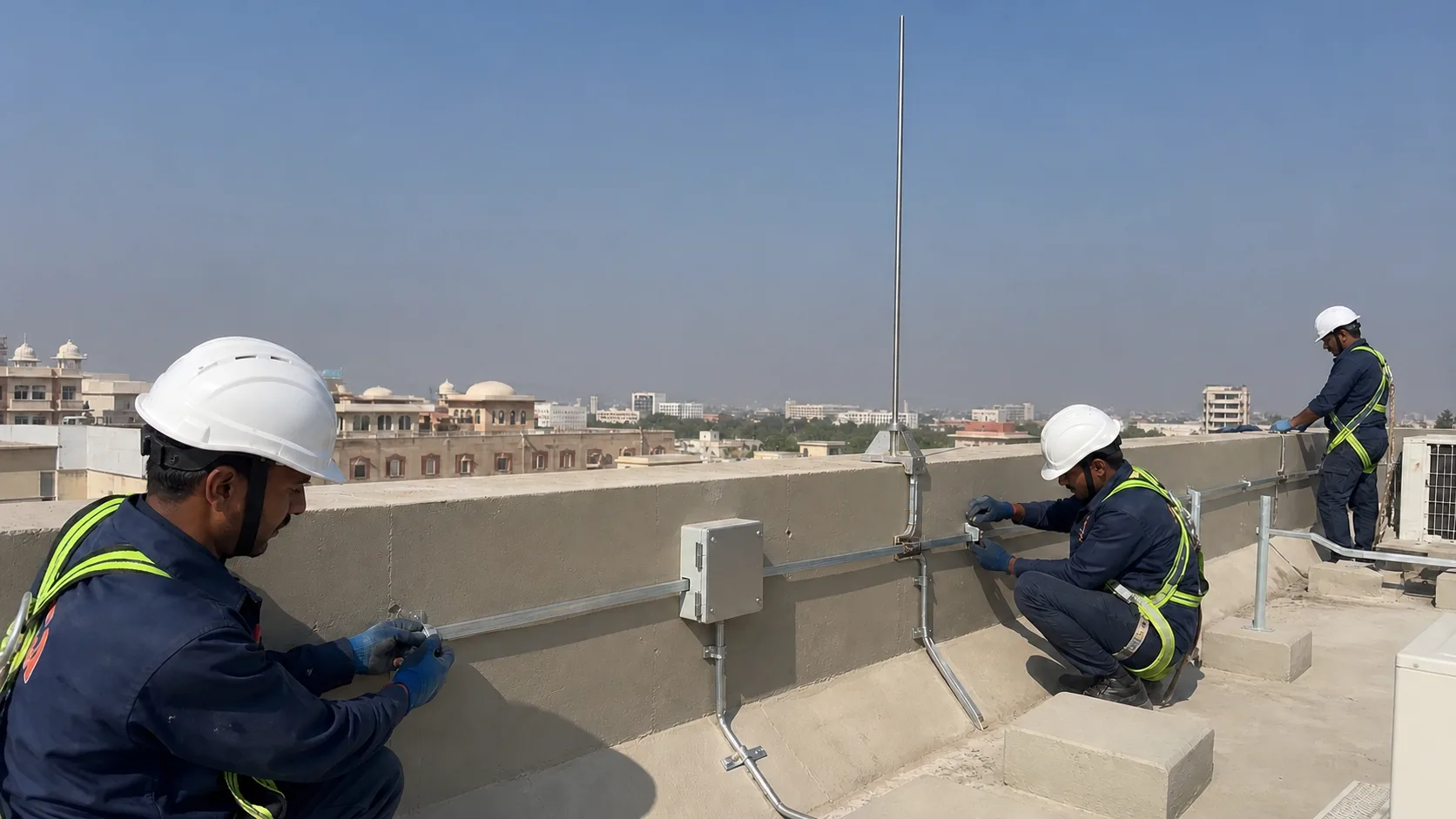
Lightning engineering service
Lightning risk assessment and LPS design in Jaipur using structure data, roof geometry, incoming services and an agreed IS/IEC 62305 scope.
Discuss the project inputsDirect answer
Risk comes first. The assessment uses the structure, occupancy, incoming services, roof equipment and surrounding exposure to set a design basis before anyone chooses a terminal.
The roof still matters. Air termination, down paths, bonding, surge protection interfaces and earth termination then need a coordinated layout drawn around the building that actually exists.
3E lists lightning risk assessment and LPS design under IS/IEC 62305. The agreed edition and deliverables belong in the proposal.
Rolling-sphere and mesh methods are listed in the company profile. Their use follows the structure-specific design.
Tanks, solar arrays and level changes alter the problem. A generic circle over an aerial image does not settle the route.
Technical view
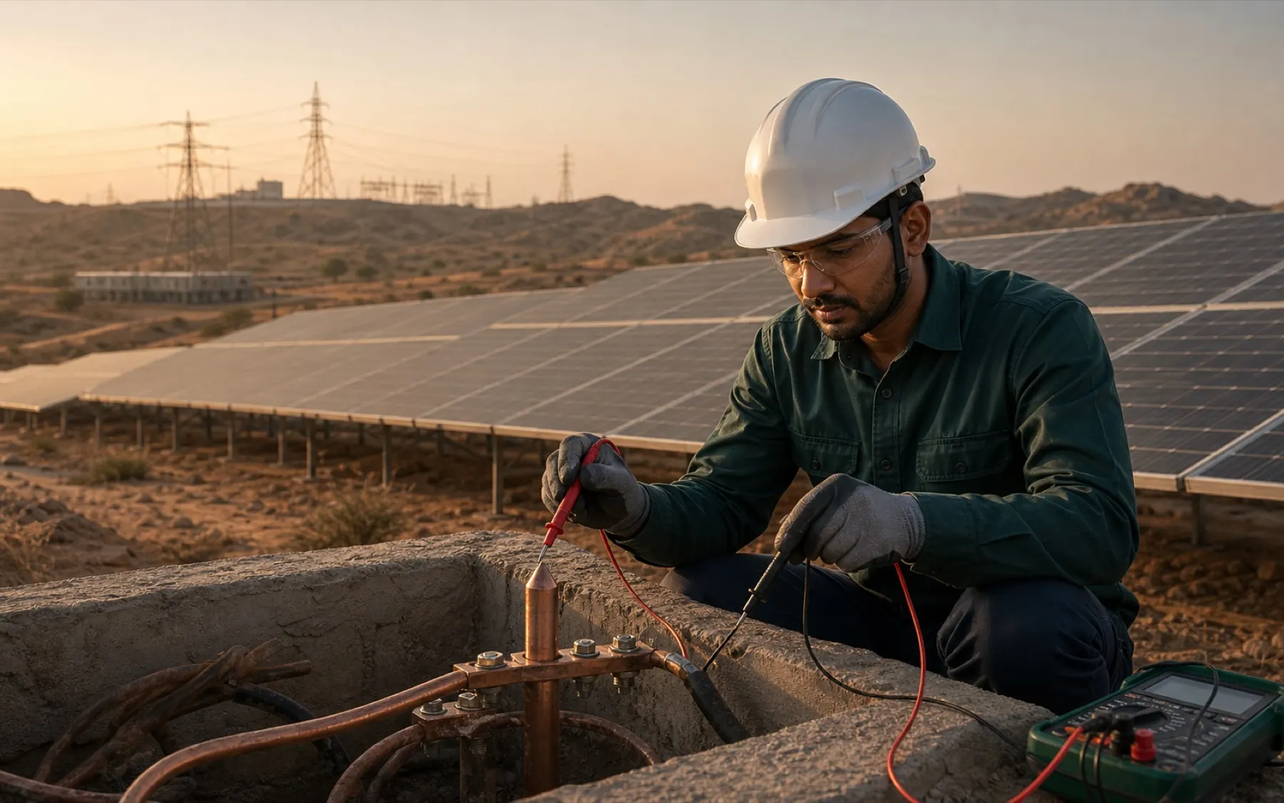
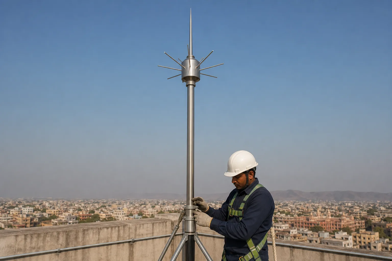
Plans are useful. Add dimensions, height, occupancy, construction, incoming power and communication services, nearby exposure and the consequence of damage to the first review.
Photographs catch the awkward parts. Roof tanks, parapets, exhausts, arrays and access routes often explain why a clean desk sketch becomes brittle when it reaches site.
They answer different questions. The assessment establishes the risk basis and required protection decisions, while the layout turns those decisions into air termination, conductors, bonds and earth interfaces.
Keep both traceable. A marked drawing should show what was assumed, where the routes sit and which details still require coordination with structure, waterproofing or electrical teams.
Roofs do not stay still. Added solar arrays, tanks, steelwork, telecom equipment or incoming services can change exposure and invalidate an old route without anyone noticing.
Damage matters too. A strike, building extension or repeated test defect is a sensible trigger for review rather than another coat of paint on the same joint.
Decision sheet
Name the output before the visit. A calculation and a marked roof plan solve different parts of the job.
Working sequence
Each stage narrows uncertainty. Product selection sits after the risk and geometry review, not before it.
Review drawings, use, incoming services and the consequence of interruption or damage.
Record levels, equipment, edges, access and possible conductor routes on the real structure.
Document the assessment assumptions and the selected air-termination method.
Mark routes, interfaces and remaining decisions for approval before installation.
Questions that change the scope
Sometimes the first review can. A site survey is still needed when the drawing misses equipment, levels, routes or incoming services.
No. Class selection is one outcome within a wider assessment and design process.
Often, yes. It changes roof geometry, metalwork, cable routes and surge interfaces.
Only when the proposal says so. Calculation, drawings, BOQ and site supervision should be named separately.
Send the real inputs
Send roof plans, elevations, site photographs, building use and incoming-service details. We will identify whether a desk review is enough or a survey is required.
Send the requirement on WhatsApp