
Neutral duty
The neutral route belongs to system and protection design. It cannot be sized from transformer appearance or price.
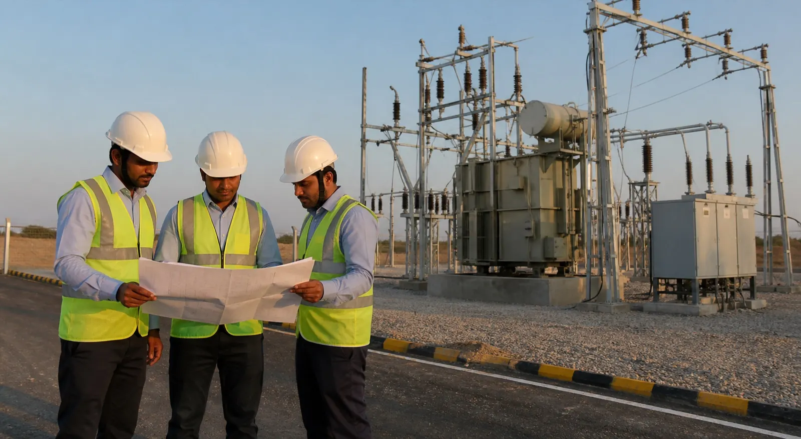
Transformer application
Understand transformer neutral and body earthing duties, design inputs, conductor identities, test links and records needed on the project drawing.
Discuss the project inputsDirect answer
The duties are different. Neutral earthing establishes the system reference and fault behaviour defined by the protection design, while body earthing bonds the transformer tank and exposed metal.
Keep the paths identifiable. Conductors, links, electrode arrangements and test records should follow the approved drawing rather than being combined at site because two chambers happen to be close.
The neutral route belongs to system and protection design. It cannot be sized from transformer appearance or price.
The tank and associated metal need a dependable protective bond. Paint and loose hardware can interrupt it.
CPRI evidence applies to the tested electrode model. One report must not be stretched across the entire range.
Technical view
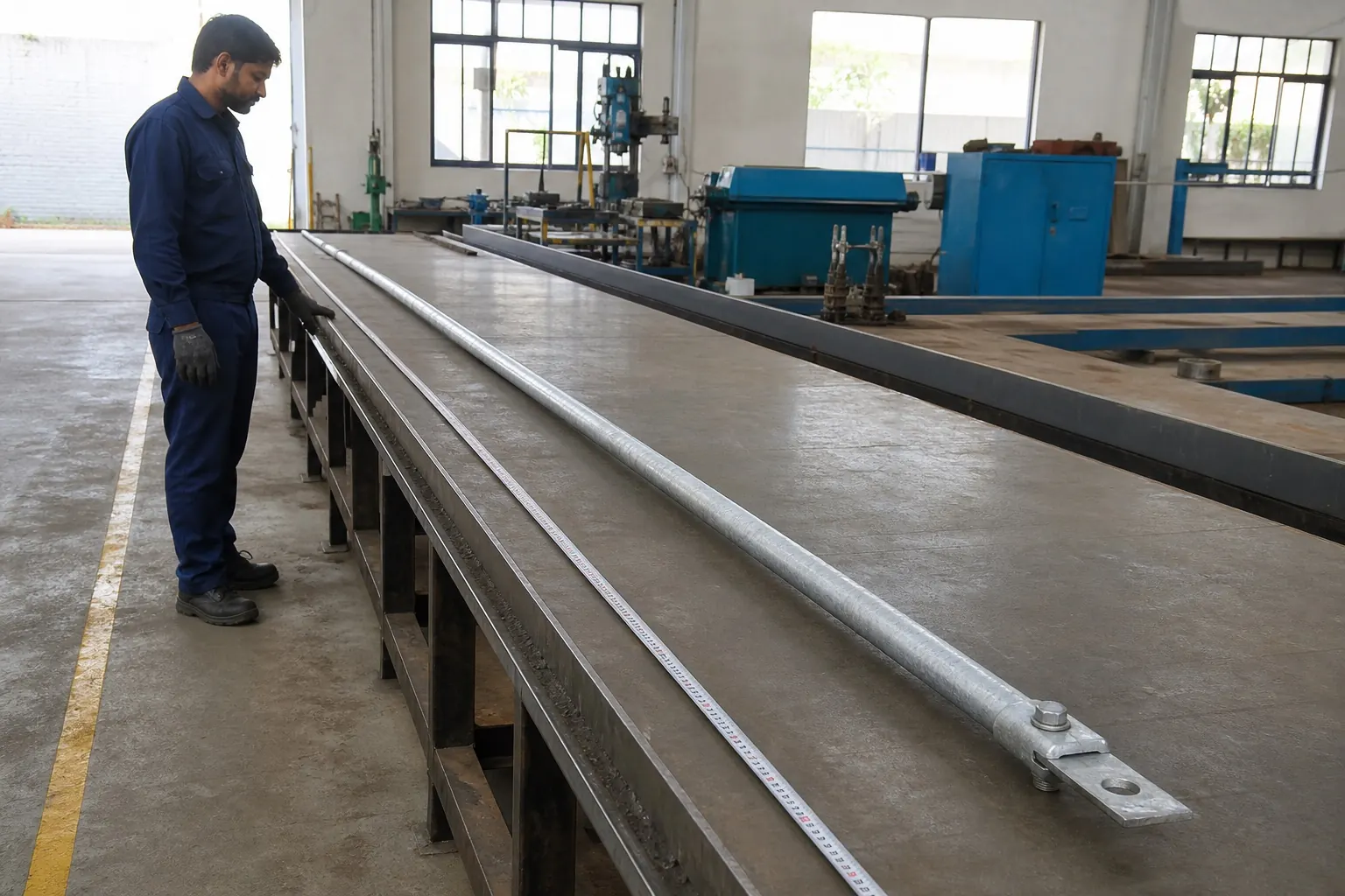
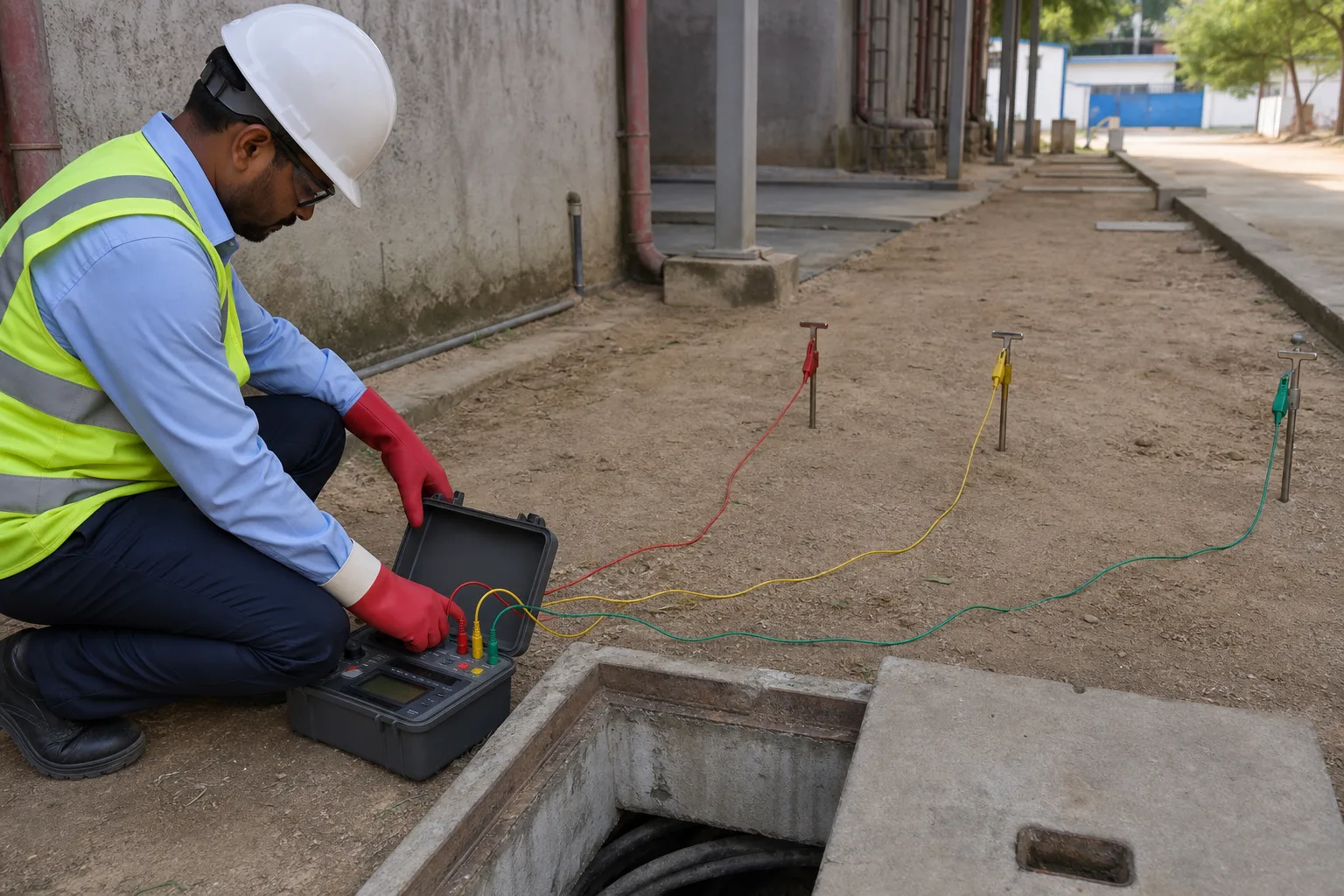
Neutral and body are not synonyms. One relates to the system reference and fault-return behaviour, while the other limits dangerous voltage on exposed conductive parts.
Protection depends on the route. Conductor section, joints, links and network connection matter alongside the buried electrode chosen for the project.
Start with the study. Transformer rating, voltage, fault current, clearing time, protection philosophy, soil and utility requirements belong ahead of electrode quantity.
Then read the site. Available spacing, grid connection, cable routes and future test access can change a neat drawing once equipment foundations are fixed.
Testing becomes guesswork. An unlabeled chamber may return a low parallel reading while the intended neutral or tank path contains a poor joint elsewhere.
Repairs become risky too. Clear links and drawings help teams isolate the correct path without disturbing an operating system they do not fully understand.
Decision sheet
Make each duty traceable. The drawing and BOQ should agree on identity, route, materials and acceptance evidence.
Working sequence
Identification is an engineering control. It prevents test results and later repairs from drifting away from the path they describe.
Use system and fault inputs to define neutral and protective bonding duties.
Mark conductors, links, electrodes and network interfaces without ambiguous labels.
Protect spacing, access and joints around foundations, trenches and cable entries.
Record each reading and continuity result against the correct duty and connected state.
Questions that change the scope
Do not improvise. The approved system design must state their arrangement and bonding.
No. Fault duty, soil, corrosion, arrangement and required evidence affect selection.
No. It belongs only to the tested model and stated test conditions.
Yes. Parallel paths can change the number and its meaning.
Send the real inputs
Send the single line, transformer data, fault and protection inputs, site layout and current earthing drawing. We will identify ambiguous duties and missing schedule fields.
Send the requirement on WhatsApp