
1. Nature of site
The basic nature and properties of soil in a given location cannot be changed without considerable expense, and careful consideration of the geology should be used to determine the best location for an earthing system.
Where there is an option, a site should be chosen in one of the following types of situations in the order of preference given:
- Wet marshy ground;
- Clay, loamy soil, arable land, clayey soil, clayey soil or loam mixed with small quantities of sand;
- Clay and loam mixed with varying proportions of sand, gravel, and stones;
- Damp and wet sand, peat.
Care should be taken to avoid a site where water flows over it (e.g. the bed of a stream) for the beneficial salts can be entirely removed from the soil in such situations.
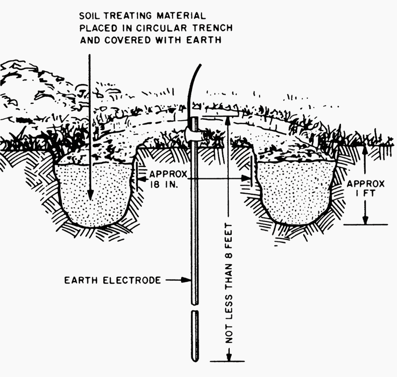
1.1 Soil treatment
In high resistivity locations or on rocky ground where long term performance is required, it may be considered necessary to utilize a conductive concrete to improve earth contact resistance around an earth rod or strip (tape) where applicable.
There are commercially available materials to achieve this effectively, but care should be taken to understand how they work during installation to ensure that they remain in contact with the rod or strip and do not shrink or swell away after drying out.
Chemical treatment of soil has environmental implications and should not be considered as a long term solution in order to meet a specified level of resistance, apart from the risk of corrosion to the earthling system. Coke breeze should also not be used due to its highly corrosive nature.
2. Soil resistivity
The resistance to earth of a given electrode depends upon the electrical resistivity of the soil. Most first approximation formulae are related to homogenous soil, which is rarely the case in practice, where the different layers of strata will affect the distribution of current passing through the electrode.
Table 1 gives examples of resistivity only. These figures are very general and should not be used to replace actual measurements made at the proposed site. They may be used to give an indication of the difficulties that one might face in preparing an adequate design at the chosen location.
Soil temperature has some effect on the upper layers of strata, but is only important under frosty conditions. Therefore any part of an electrode system which is less that 0.5 m below ground level should not be considered to be effective.
Table 1 – Examples of soil resistivity in Ωm

3. Measurement of soil resistivity
Soil resistivity may be measured in a similar manner to the establishment of the resistance of the earth electrode.
- Drive four equally spaced test electrodes to a depth of not greater 5% of their spacing apart a. It is important to ensure that their resistance areas do not overlap (Figure 2)
- Pass current between the two outer electrodes
- Measure the earth potential between the two inner electrodes
The resistance R should be taken as the ratio of the voltage between the inner electrodes and the current between the outer electrodes. In homogenous soil the average resistivity ρ in ohm metres (Ωm) may be taken as:
ρ = 2 π a R
where:
- a is the spacing between electrodes, in metres (m);
- R is the resistance measured between the middle electrodes, in ohms (Ω).

The resistivity so determined applies to an electrode separation distance a, which is related to the depth of investigation. By repeating the measurement with increasing values of a, the apparent resistivity involving greater depths may be assessed.
This may be taken as an indication of the possible gain from driving deeper rods, etc., into strata of a lower resistivity to get the required resistance.
Four equally spaced test spikes should be driven to a depth of up to 1 m, the depth not exceeding 5% of their separation a.
It is important to ensure that their resistance areas do not overlap. Current should be passed between the two outer electrodes and the resistance R may be found as the ratio of the voltage between the inside electrodes to the current conducted through the outside electrodes.
EXAMPLE – If the distance a between electrodes is 1 m the constant for the test setup is calculated as (2 × 3.14 × 100) cm = 628 cm. If the instrument reads 40 Ω the earth resistivity is (40 × 628) Ωcm = 25 120 Ωcm.
It should be noted that environmental conditions such as temperature have an impact on earth resistivity with a corresponding decrease in resistivity as temperature rises.
4. Types of earth electrodes and their resistance calculation
An earthing system should be of the highest integrity and of robust construction to ensure that it remains safe and will not endanger the health and safety of persons or their surroundings. The majority of the formulae presented in this section relate to low frequency currents and high frequency examples are not included.
It is therefore important to recognize this issue if a long horizontal tape or bare cable is being considered for producing a low earth resistance, even though the impedance will ultimately be limited to a final value (see Figure 4).
Earthing systems should consist of copper conductors, copper clad or austenitic steel rods of appropriate dimensions, cast iron plates, or steel piles used individually or connected together in combination to form a single local earth electrode system.

The formulae which follow are all based on homogeneous soil conditions, so in most practical situations only give a reasonable idea of the problems (within 15% accuracy) that might exist if the strata is such that the resistivity changes at different levels.
However, onsite resistivity testing should always be carried out prior to carrying out an earth system design and installation.
The effect of shape on an electrode resistance is related to the current density around the particular electrode considered. To obtain a low overall resistance the current density should be as low as possible in the medium surrounding the electrode.
This may be achieved by making the dimensions in one direction large by comparison to the other two. Thus a pipe rod or strip has a much lower resistance than a plate of equal surface area.
a) Plates
The approximate resistance to earth of a plate R in ohms (Ω) may be calculated from:

where:
- ρ is the resistivity of the soil (assumed uniform), in ohm metres (Ωm);
- A is the area of one face of the plate, in square metres (m2).
Plates, if used, should be installed as small units of not greater than 1.2 m × 1.2 m connected in parallel vertically and at least 2 m apart. The minimum ground cover should not be less than 600 mm and ideally the surrounding soil should be damp.
Where the plate is placed in a cut out slot, e.g. in a chalk bed near the surface, the slot should be big enough to allow at least 300 mm thickness of soil or other conducting low resistivity medium cover around the whole plate. This requires careful assembly during installation to ensure that the bottom of the plate is resting in the medium used and not on the chalk or high resistivity substrata.
NOTE! For conventional sizes, the resistance is approximately inversely proportional to the linear dimensions, not to the surface area, i.e. a 0.9 m × 0.9 m plate has a resistance approximately 25% higher than a 1.2 m × 1.2 m plate.
b) Rod electrode
The resistance of a rod Rr in ohms (Ω) may be calculated from:

where:
- ρ is the resistivity of soil, in ohm metres (Ωm);
- L is the length of the electrode, in metres (m);
- d is the diameter of the rod, in metres (m).
NOTE! – Change of diameter has little effect on the overall value of resistance, and the size is more governed by the mechanical strength of the rod to withstand being mechanically driven when deep earth rods are required e.g. to depths of 20 m or more.
c) Strip or round conductor electrodes
This section deals only with a straight run of conductor. Other shapes are not covered here.The resistance Rta in ohms (Ω) of a strip or round conductor may be calculated from:
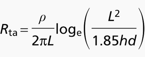
where:
- ρ is the resistivity of soil, in ohm metres (Ωm);
- L is the length of the electrode, in metres (m);
- h is the depth of the electrode, in metres (m);
- d is the diameter of the round conductor or diameter of the equivalent cross sectional area of the strip, in metres (m).
When two or more strips in straight lengths, each of length L in meters (m) and a separation distance s metres are laid parallel to each other and connected together at one end only the combined resistance may be calculated from the following equation:
Rn = F R1
where:
- Rn is the resistance of n conductors in parallel, in ohms (Ω)
- R1 is the resistance of a single strip of length L, calculated from the preceding Rta equation, in ohms (Ω).
- F has the following value:
- For two lengths: F = 0.5 + [0.078(s/L)] − 0.307
- For three lengths: F = 0.33 + [0.071(s/L)] − 0.408
- For four lengths: F = 0.25 + [0.067(s/L)] − 0.451
- Provided that 0.02 < (s/L) < 0.3
d) Mesh
The resistance of a mesh (grid) Rm ohms (Ω) may be calculated from:
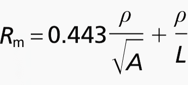
Where:
- ρ is the resistivity of soil, in ohm metres (Ωm);
- A is the actual area covered by the mesh, in square metres (m2);
- L is the total length of strip used in the mesh, in metres (m).
e) Resistance of an electrode encased in low resistivity material, e.g. conducting concrete
The resistance of a backfilled electrode Rb in ohms (Ω) may be calculated from:
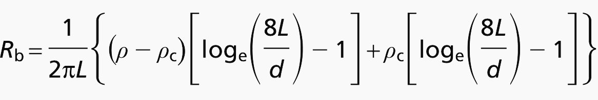
where:
- ρ is the resistivity of soil, in ohm metres (Ωm);
- ρc is the resistivity of the conducting material used for the backfill, in ohm metres (Ωm);
- L is the length of rod, in metres (m);
- d is the diameter of the rod, in metres (m).